In applications, the issue of tantalum capacitor explosions is frequently encountered, especially in switching power supplies and LED drivers. Tantalum capacitor explosions are also quite hazardous, which makes some engineers somewhat reluctant to use them. This article briefly analyzes the causes of tantalum capacitor failures.
Mainly the following 5 points:
- Failure caused by excessive voltage in low-impedance circuits
- Excessive peak output current
- Tantalum capacitor ESR is too high or AC ripple is too large
- Tantalum capacitor leakage current is too high, leading to insufficient voltage withstand capability
- Failures caused by production and assembly
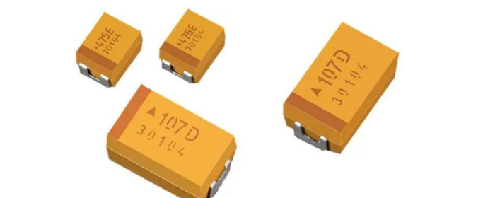
What are Tantalum Capacitors
The full name of a tantalum capacitor is Tantalum Electrolytic Capacitor, first developed by Bell Labs in the USA in 1956. A tantalum capacitor is manufactured starting with a porous anode slug made from pressed and sintered, high-purity tantalum powder. This is followed by the formation of a dense tantalum pentoxide (Ta₂O₅) dielectric film through anodization, and the subsequent application of a cathode material like manganese dioxide to complete the structure.

Fig 1. Tantalum capacitor construction
Most tantalum capacitors have very similar anode structures, composed of high-purity solid tantalum powder. The tantalum powder is sintered at high temperatures, converting granular tantalum into a porous structure with a very large surface area to achieve higher capacitance. What distinguishes tantalum capacitors is their cathode system. There are three types of tantalum capacitors: Manganese Dioxide (MnO2), Conductive Tantalum Polymer, and Wet Tantalum capacitors.
Compared to aluminum electrolytic capacitors, they feature smaller size, higher quality, and stable parameters. However, they also have some disadvantages, such as relatively lower capacitance and rated voltage. Tantalum capacitors generally do not suffer from issues like drying out or dielectric degradation during long-term storage without charge.
Causes and Solutions of Tantalum Capacitor Failures
1. Voltage Overstress in Low-Impedance Circuits
This is the most classic and dangerous failure scenario for tantalum capacitors. The core of the problem lies in surge voltage and circuit impedance.
In low-impedance circuits like DC-DC converters, the switching transistor generates extremely short-duration (microsecond level), high-energy voltage spikes during turn-on and turn-off instances. Due to the low circuit impedance, these spikes cannot be effectively absorbed or limited and are directly applied across the capacitor terminals. Even if the average working voltage is within the rated value, the instantaneous pulse voltage may far exceed the withstand limit of the capacitor's dielectric layer (Tantalum Pentoxide, Ta2O5), causing instantaneous breakdown of the dielectric layer and forming a short circuit.
Solution: Strict voltage derating. In low-impedance circuits with high surges, the operating voltage should not exceed 1/3 of the capacitor's rated voltage. The derating factor needs to be precisely determined based on the specific circuit's impedance, power rating, and ripple level.
2. Excessive Peak Output Current
The peak surge current flowing through the capacitor I_peak ≈ V / ESR (where ESR is the Equivalent Series Resistance). During power supply startup or sudden load changes, the huge instantaneous current causes Joule heating within the capacitor's tantalum core-dielectric layer system. If the current exceeds the safe threshold, the accumulated heat cannot dissipate quickly enough, leading to local overheating, which damages the insulation of the dielectric layer and causes thermal breakdown.
Solution: Select models with sufficiently low ESR and whose peak current withstand capability (I_peak) meets the circuit requirements. For scenarios involving high current charge/discharge, one must not only consider capacitance and voltage rating but also check the surge current rating in the datasheet.
3. Thermal Failure Due to Mismatch Between ESR and AC Ripple
When AC ripple current flows through a capacitor with ESR, it generates power loss P = I_ripple² × ESR, manifested as heat. If the ripple current is too high, or the capacitor's ESR is too large, the generated heat causes the capacitor's core temperature to rise continuously. Once the temperature exceeds the thermal equilibrium limit of the tantalum core-manganese dioxide system, it triggers "thermal runaway" – rising temperature reduces resistance, increasing current, which generates more heat, eventually causing the capacitor to burn or explode.
Solution: In circuits with high ripple currents, such as filters, it is essential to select tantalum capacitors with low ESR (like polymer tantalum capacitors) and ensure their rated ripple current is greater than the actual ripple value in the circuit.
4. Excessive Leakage Current and Insufficient Actual Voltage Withstand Capability
Leakage current reflects the insulating property of the dielectric layer. If the dielectric layer of a tantalum capacitor has defects or impurities, its leakage current will be relatively high. Under high field strength, excessive leakage current generates additional heat, reducing the actual insulating strength of the dielectric layer, creating a vicious cycle of "thermal breakdown" and "field-induced breakdown." Especially at high temperatures, the insulating property of the dielectric layer naturally decreases; if the leakage current index is poor, the actual withstand voltage can be far lower than the room temperature rating.

Fig 2. The presence of crystals on the tantalum anode signifies a defective dielectric layer.[1]
Solution: Choose brand products with low leakage current and high reliability, and follow voltage and temperature derating specifications in design. The lower the applied voltage, the more exponentially the leakage current decreases.
5. Thermal and Mechanical Stress During Production and Assembly
During manual soldering, if the soldering iron temperature is too high (e.g., >300°C) or the dwell time on the solder joint is too long, significant thermal stress is conducted through the leads into the capacitor's interior. This can cause various issues:
① Micro-cracks inside the sintered tantalum core;
② Compromised bond strength between the tantalum core and the lead frame;
③ Damage to the dielectric layer due to thermal shock.
These damages might not be immediately detectable during testing but significantly reduce long-term product reliability, becoming potential causes of early failure.
Solution: Strictly adhere to the reflow soldering profile. If manual soldering is necessary, use a temperature-controlled soldering iron, solder quickly, and preheat the board to avoid local overheating.
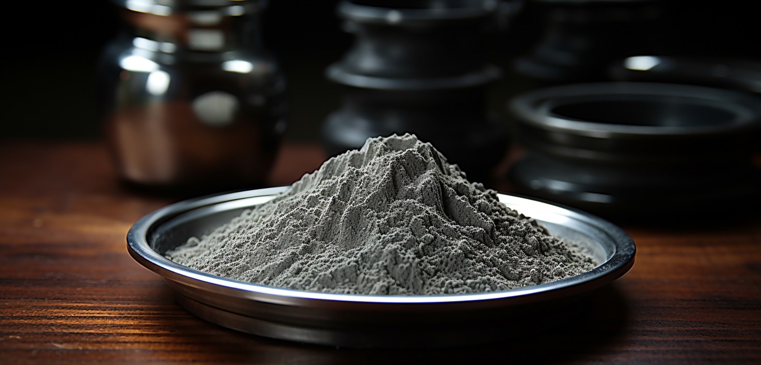
Tantalum Powder – Determining Tantalum Capacitor Reliability
The five major failure modes discussed above, whether voltage overstress, thermal runaway, or dielectric layer breakdown, ultimately have their physical point of occurrence on the core of the tantalum capacitor – the porous anode body sintered from tantalum powder. The quality of the tantalum powder directly determines the inherent quality of the dielectric layer and is the foundation of capacitor reliability.
1. The Fundamental Conflict Between Specific Capacitance and Dielectric Layer Thickness
Capacitance C ∝ A / d (A is the surface area, d is the dielectric layer thickness). To achieve high capacitance within a tiny volume, high specific capacitance (CV/g) tantalum powder must be used. High specific capacitance means the tantalum powder has a larger surface area per unit mass. However, under the same formation voltage (the voltage used during the anodization process to form the dielectric layer), the thickness d of the dielectric layer (Ta2O5) is essentially fixed.
Using tantalum powder with higher specific capacitance results in a capacitor with a relatively thinner dielectric layer. A thinner dielectric layer means it withstands a higher electric field strength under the same operating voltage, naturally increasing the risk of breakdown. This is the fundamental reason why high-capacitance, small-volume tantalum capacitors require stricter voltage derating.
2. Purity and Defects
Trace metal and non-metal impurities in the tantalum powder, such as Fe, Na, O, C, N, are "disruptors" of the perfect dielectric layer.
During the dielectric layer growth process, impurity regions may prevent the formation of a dense, uniform Ta2O5 layer, thus becoming "weak spots" in the dielectric. These defect sites are prone to localized leakage current concentration and breakdown under high electric fields, becoming the initiation source for the entire capacitor's failure. Therefore, ultra-high purity is an essential attribute of high-end, high-reliability tantalum powder.
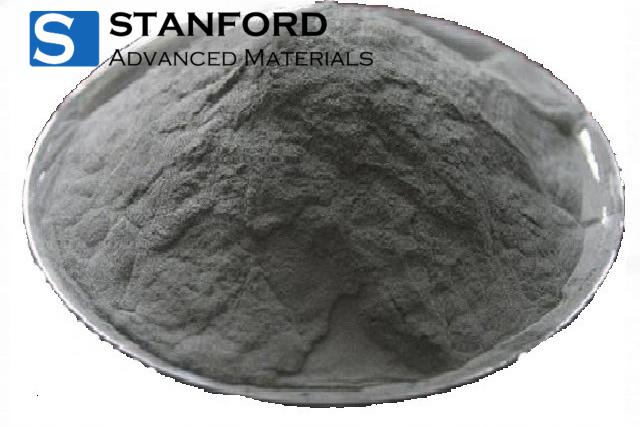
Stanford Advanced Materials (SAM) provides capacitor-grade tantalum powder with purity levels as high as 99.999%.
3. The Impact of Particle Morphology and Structural Stress
The particle shape (spherical, dendritic, etc.) and particle size distribution of the tantalum powder determine the microstructure of the sintered porous anode.
Irregular particles and a broad particle size distribution can lead to uneven sintering density, easily forming local sharp protrusions. According to the principle of corona discharge, the electric field concentrates highly at these protrusions, generating local field strength far higher than the average value, greatly accelerating the aging and breakdown process of the dielectric layer. Therefore, regular particle morphology and a narrow particle size distribution are crucial for forming a uniform and robust dielectric layer.
Conclusion
The failure of tantalum capacitors often manifests as circuit application issues, but the root cause is often deeply embedded in their material essence. A capacitor made from low-purity, irregular, ultra-high specific capacitance tantalum powder carries a significantly higher inherent risk of failure compared to a product built from high-quality tantalum powder, even if the circuit design is perfect.
[1] Qazi, Javaid Iqbal. “An Overview of Failure Analysis of Tantalum Capacitors.” EDFA Technical Articles (2014): n. pag.


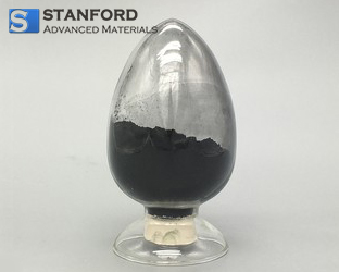
 Oxide Powder (1).jpg)